Introduction to the simulation structure
This page provides an introduction to the three-layered structure of a PsxCad simulation and the associated variants of symbols, that correspond to this structure. There are various libraries available and designable. In this introduction only symbols from the PSS library will be used as illustrative examples.
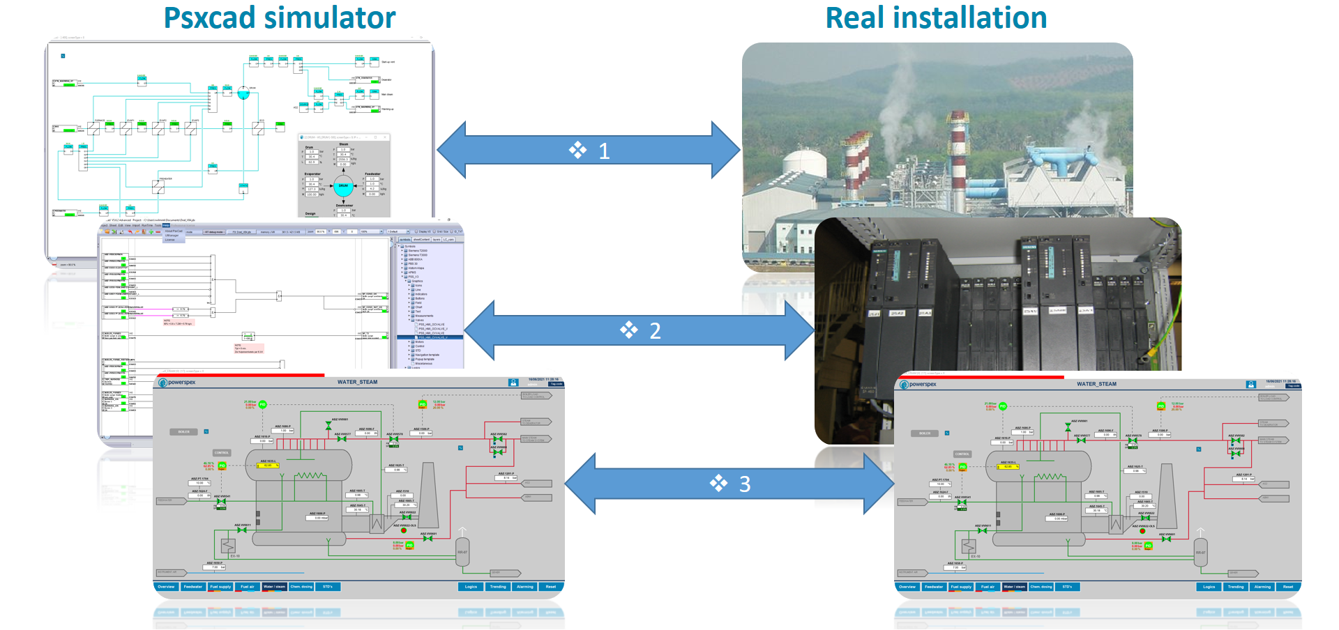
The three-layered structure within a PsxCad simulation
Simulations made with PsxCad can be composed of three layers namely:
These three layers are applicable to a real process with an industrial automated system. Depending on the specific project requirements, each layer can be basic or conceptual up to detail and complex.
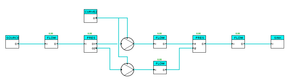
1. Process Model and Field Simulation Layer
The first layer simulates the real field installation. In this simulation of the real field installation, it is possible to differentiate between simulation of the real field installation as a process installation, pipelines, vessels, heat exchangers, etc., (Process Model) and simulation of field components directly connected to the PLC/DCS, valves, pumps, fans, etc., (Field Simulation).
Process Model
The Process Model simulates physical dynamic processes in the field. Symbols designed for the Process Model include theoretical approaches and physical calculations. The accuracy and completeness of the simulation depends on intended application and outcome of the simulation.
Field Simulation
The Field Simulation simulates the behavior of field components such as valves, pumps and fans, with e.g. stroke time, start/stop time, feedback signals. It manages received command and control signals from the Logics Layer and provides feedback signals regarding the statuses of the components in the field and covers the conversion to Process Model suitable signals. The Field Simulation complexity and completeness depends on the desired simulation and testing capabilities.
It’s important to note that in some cases, simulations may deviate from this set-up. Controlling components can also be set up directly to the process model for quicker engineering however with less simulation possibilities.
Since it is possible for PsxCad to connect to a PLC or DCS system, this layer alone can be used for testing an existing PLC/DCS system.
2. Logics Layer : PLC/DCS logics
The second layer simulates the overall automation in the PLC/DCS, with control, logics and safety functions. Replications of PLC/DCS software modules can be created and used for the design or replication of a PLC/DCS system. Various programming operators can be applied here to design or emulate logics.
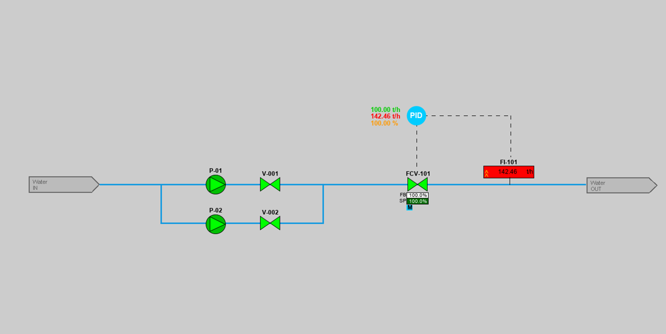
3. Screens Layer : HMI / SCADA
The third layer covers the human machine interface and it can simulate various HMI and SCADA applications related to the PLC/DCS system. HMI or SCADA screens can be designed here or recreated with precision. This layer can emulate screens, symbols, navigation, pop-ups, alarming systems, and trendlines.
Symbolic variants within a library
Within each layer, various types of symbols are designed for specific purposes. They are discussed below.
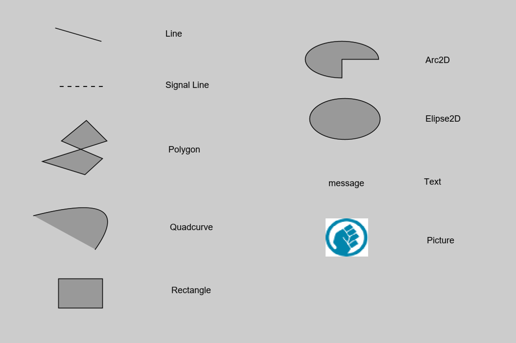
Basic symbols
Basic symbols serve as the fundamental building blocks for other symbols within PsxCad. These symbols are used to design and visualize various symbols, which is why these are present across all layers. Notably, the signal line symbol is exclusively found on the logics, field simulation, and process model layers, since its solely used to connect symbols containing logic content.
Graphic symbols
Graphic symbols are solely used in the Screens Layer. These symbols lack logic content but often have some dynamic function build within them. Influenced by logic symbols, they can alter their appearance.
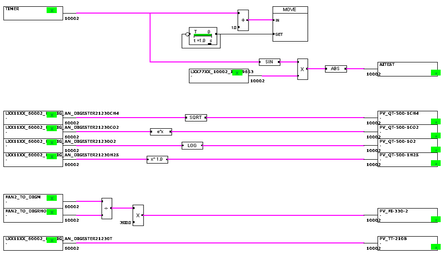
Logics symbols
Logic symbols primarily consist of programming operators used to build up your logics within the Logics Layer and optional in the Field Simulation. These contains mathematical operators and functions, various logic gates, switches, timers, delays, comparators, ramps, signal converters, symbols for constructing state-transition diagrams (STDs), conversions, comments and revisions.
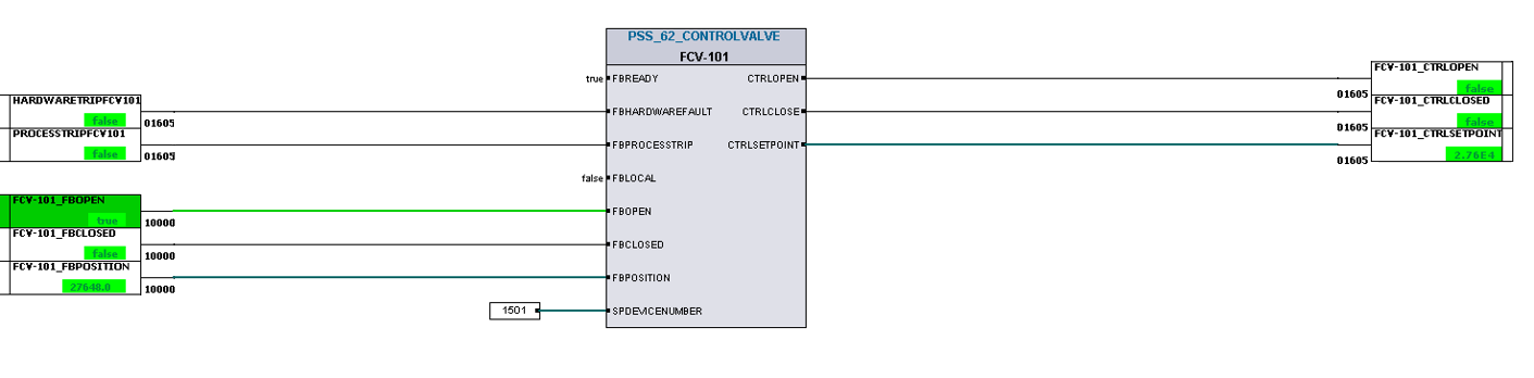
Software module symbols
Software modules are symbols used within the Logic Layer that mimic specific sections of PLC/DCS code with designated functionalities. These symbols are modular in design and easily reusable, such as function blocks of Siemens PLCs. Different terminologies, such as “typicals” or “control modules” can be used for these symbols.
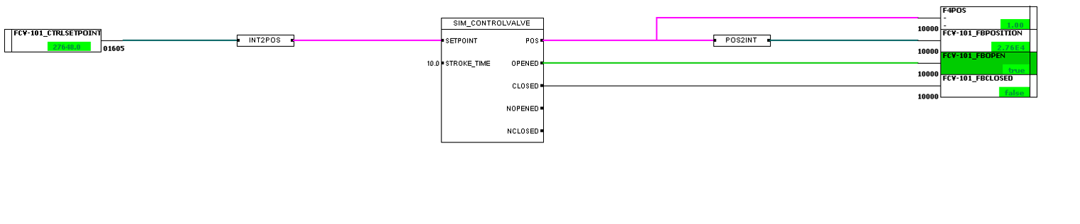
Field Simulation symbols
Field Simulation symbols are used in the layer Field Simulation and process modeling. In contrast to certain software modules that simulate the response to these software modules, field simulation symbols emulate physical components within the field.
Process Model symbols
Process Model symbols are used in the layer for field simulation and process modeling. They encompass theoretical approaches and physical calculations that enable the dynamical processes within the simulation. These symbols can vary to emulate specific situations, with their color typically indicating the medium they represent.