Modbus TCP
PsxCad can communicate with Modbus devices using the Modbus TCP protocol. The software supports both client mode and server mode. In client mode, PsxCad can access data to or from a Modbus device in Runtime mode. Server mode allows other Modbus devices or applications to access Psxcad Runtime data. More information about Modbus can be found in the official spec.
Client mode
To get PsxCad to connect to a Modbus server or device, you will need to enter the PLC address in the logic content window J under the column PLC_address. It is recommended to limit Modbus usage to IN or OUT symbols, This allows for a better overview of Modbus values and makes the behavior of the symbols predictable.
Using an IN symbol will read values from the Modbus device, this called The OUT symbol will write values to the device.
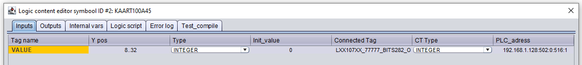
The syntax for entering a Modbus connection follows this structure:
192.168.1.128:502:0:516:1
{server address}:{port}:{Unit ID}:{Modbus address}:{number registers}
Server address
The address of the Modbus server you want to connect to. This can be either an IP address '192.168.1.100' for example or a DNS name 'plc.example.com', listening to a PsxCad Modbus server on localhost is not supported, you can use the LAN IP instead.
Port Number
The default port for the Modbus TCP protocol is 502, if you are using a non-default port number you can enter it here.
Unit ID
By default, the Unit ID should be 0, If you are using the Modbus device as a Modbus RTU gateway the value could be different, check the manufacturer manual for the correct Unit ID.
Modbus address
The Modbus address is a device-specific number that maps PLC parameters to Modbus Using the device manufacturer manuals you should be able the find the address.
Number of registers
This number indicates the number of registers of the communicated tag. For 16 bits this will be '1' register and for 32 bits it will be '2' registers. 16 bits will correspond to an integer signal type and 32 bits will come across one with a double signal type.
| Modbus type | PsxCad type | # of registers |
|---|---|---|
16-bit word |
Integer |
1 |
32-bit word |
Double |
2 |
| Modbus addresses that are 32-bit words (Doubles) use two registers, this means that you don’t read the second register. |
Reading with coils
Modbus allows reading and writing of single bits, These single-bit values are called coils. In order to use these in Psxcad you need read all 16-bits and essentially single bits from a single-byte register.
For an example have a look at the how the setup modbus guide
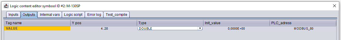
Server mode
In server mode, PsxCad enables access to runtime values by running a Modbus server. This allows Modbus clients to communicate with PsxCad runtime. When runtime mode is started and the project contains Modbus addresses, PsxCad will create a Modbus server automatically.
The Modbus addresses can be mapped by entering a prefix with a number in the PLC_address column of the logic content window with the following structure:
MODBUS_123
MODBUS_{Modbus address}
The logic content window is accessible by using the short-cut J on a symbol. See the example below in Figure 2.
It is recommended to limit Modbus usage to IN or OUT symbols, This allows for better overall findability of Modbus values and makes the behavior of the symbols predictable. Using an IN symbol will read values from the Modbus server, this called The OUT symbol will write values to the server.
|
It may be that the program or device on the other side of the Modbus uses an other counting method than PsxCad does, so the Modbus addresses on each side may not match. This is why it is important to test and see how the logic in communications you are setting up works. |
About datatypes
Data of a Modbus server may contain different kind of datatypes. A Modbus address points within the data to a 16-bit register. The 16 bit register has the same length of bits of a normal integer. A boolean has a data size of 1 bit, so booleans will fit 16 times into this register. A float has a data size of 32 bits and will occupy two addresses with a 16-bit register. For floats the Modbus address will point to the first register, but will then also occupy the register after it. Thus you should take steps of two when numbering the Modbus address for floats in order to don’t mess up the second half of a float.
In PsxCad a float is actually used as double. The underlying programming language of PsxCad is Java, which automatically treats floats as doubles. Therefore, you will only work with doubles in PsxCad. However, when communicating with Modbus devices, PsxCad converts all doubles to floats, because this is more common for other platforms and devices.
About PsxCad’s modbus server
The Modbus server within PsxCad can only read or write, not both at the same time. If a register is written on the other side of the Modbus communication, it can only be read in PsxCad and if PsxCad writes a register, it can only be read on the other side. With other Modbus PLC or devices this might be different and who is reading or writing what might not be a problem.
|
When runtime is closed, PsxCad loses all data within the Modbus. Especially for registers read only by PsxCad, this is a problem. The data is then reset to zero when Runtime in PsxCad is restarted. This can be annoying, but a possible good solution is to see the Modbus as a pass-through hatch and write the read data directly with a triggered MOVE symbol to tags independent of the Modbus and store the data there. |
PsxCad indicates at runtime on the control box that a Modbus server is active when the Modbus server is successfully set up. See the figure below.
