Logic symbols
On this page you can find explanations for usage and descriptions of each logic symbol in PsxCad.
Input / Output
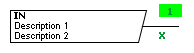
IN
 The IN symbol functions as an input on a logic page. On the lower right corner of the symbol, the source page number is displayed.
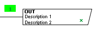
OUT
 The OUT symbols functions as an output on a logic page. On the lower right corner of the symbol, the source page number is displayed.
VAR
 The VAR symbol functions as a variable that is used on a logic page. It holds an output that is able to connect to multiple inputs. This makes it practically the same as the function of the IN symbol. The benefits of this symbol lie within documentation. As the user so chooses, they can vary between the use of IN and VAR symbols to better clarify their code. For example the VAR symbol could be used solely for constants or variables that will never be overwritten in the program, just to set them apart from the many IN symbols.
FX_IN
 The FX_IN symbol functions as an input that is only used on typical pages. When a typical block is generated from a typical page, PsxCad will configure the FX_IN symbols on the page as inputs for the block. When using normal IN and OUT symbols on a typical page, they will generate as internal variables.
FX_OUT
 The FX_OUT symbol functions as an output that is only used on typical pages. When a typical block is generated from a typical page, PsxCad will configure the FX_OUT symbols on the page as inputs for the block. When using normal IN and OUT symbols on a typical page, they will generate as internal variables.
IN_ARRAY
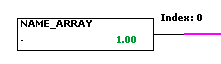
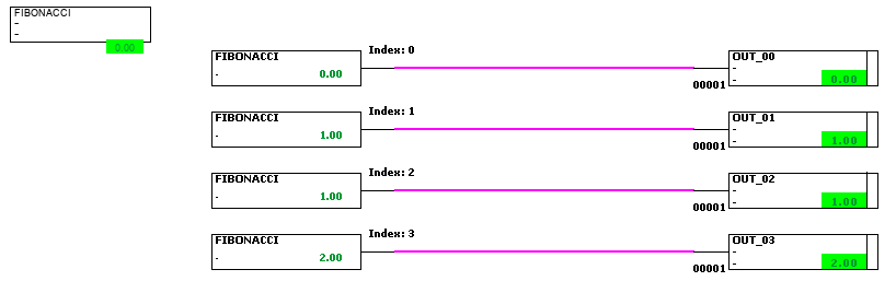
The IN_ARRAY, whose full name in the symbol library has the form of IN_ARRAY_XX (with 'XX' corresponding to a numeric value), is a symbol similar to the IN symbol. It uses the variable given by its name and extracts a double value from its array. The specific value extracted will be dependant on which IN_ARRAY symbol is chosen. The numeric value of XX represents the index of the array value extracted. The index will also be shown through the text on the top-right of the symbol. When an index is chosen that does not exist within the specified array, the value -1 will be given.
An example of the IN_ARRAY symbols is given in the following figure.
Constants
CONST_TRUE
 The CONST_TRUE symbol functions as a Always True on a logic page. This means that the output of this symbol is a boolean that is always set to true.
CONST_FALSE
 The CONST_FALSE symbol functions as a Always False on a logic page. This means that the output of this symbol is a boolean that is always set to false.


Logics
FLANK
 The FLANK symbol functions as a positive flank on a logic page, that sets its output boolean to true for one cycle when its input boolean changes from false to true.
SET_RESET
 The SET_RESET symbol functions as a Set/Reset flip-flop, that sets its output value to true when it receives a true on its S input (set) and resets its output value to false when it receives a true on its R input (reset). A Set/Reset flip-flop has a dominant input for resetting, meaning when it receives a true on both inputs it will reset its boolean output to false.
RESET_SET
 The RESET_SET symbol functions as a Reset/Set flip-flop, that sets its output value to true when it receives a true on its S input (set) and resets its output value to false when it receives a true on its R input (reset). A Reset/Set flip-flop has a dominant input for setting, meaning when it receives a true on both inputs it will set its boolean output to true.
Logic Gates
NOT
 The NOT symbol functions as an NOT operator, which is a logic gate that inverts its input signal to get its output. See the truth table below as example.
| Input | Output |
|---|---|
0 |
1 |
1 |
0 |
AND
 The AND symbol functions as an AND operator, which is a logic gate that needs all of the incoming signals to be true to return a true for its output. See the truth table below as example. This symbol can handle multiple inputs and outputs, due to its left and right boundaries containing a plane for inputs and outputs.
| Input A | Input B | Output |
|---|---|---|
0 |
0 |
0 |
0 |
1 |
0 |
1 |
0 |
0 |
1 |
1 |
1 |
OR
 The OR symbol functions as an OR operator, which is a logic gate that needs any of the incoming signals to be true to return a true for its output. See the truth table below as example. This symbol can handle multiple inputs and outputs, due to its left and right boundaries containing a plane for inputs and outputs.
| Input A | Input B | Output |
|---|---|---|
0 |
0 |
0 |
0 |
1 |
1 |
1 |
0 |
1 |
1 |
1 |
1 |
XOR
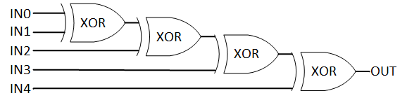
 The XOR symbol functions as an XOR operator, which is a logic gate that requires both inputs to be different before it returns a true output. This symbol can handle multiple inputs and outputs, due to its left and right boundaries containing a plane for inputs and outputs. When using more than two inputs, the symbol will generate its output by cascading multiple XOR operators. For an example of this, see Figure 2. This results in the symbol generating a true output when an uneven amount of inputs are true.
| Input A | Input B | Output |
|---|---|---|
0 |
0 |
0 |
0 |
1 |
1 |
1 |
0 |
1 |
1 |
1 |
0 |
Switches
SELECT
 The SELECT symbol functions as a selector between two input values as determined by a third boolean input on top of the symbol called a switch. When the switch input is false it returns the upper value and otherwise the lower value. At the bottom of the symbol there is a boolean output meant to pass on the switch input to another symbol. This allows the user to stack SELECT symbols a top of each other.
MOVE
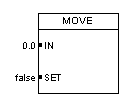 The MOVE symbol functions as an Move instruction, meaning that its tag only gets written when its boolean input "SET" is true. The tag will be written by a double (or integer) value given by the input "IN". Notice it displays no output. This is because, just like a OUT symbol, the resulting value is applied to its tag.
Timers
TIMER_ON
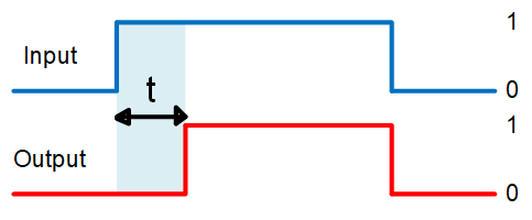
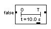
 The TIMER_ON symbol functions as a on-delay timer (TON), meaning when the input signal changes from false to true the output signal will experience a delay for an certain amount of time before it follows the input. See Figure 3 for a schematic view of this effect. It recognizes the change in value by remembering the input signal from the previous scan-cycle and comparing this to its current input signal. If a true on the input returns to a false before the ending of the delay is met, then nothing will happen to the output signal. At the lower boundary there is another output. This gives the double value of the running time, which runs until the time of the delay is met. Adjusting the delay time is done by changing the tag "T_VALUE" within the logic content of the symbol.
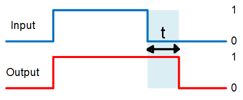
TIMER_OFF
 The TIMER_OFF symbol functions as a off-delay timer (TOF), meaning when the input signal changes from true to false the output signal will experience a delay of an certain amount of time before it follows the input. See Figure 4 for a schematic view of this effect. It recognizes the change in value by remembering the input signal from the previous scan-cycle and comparing this to its current input signal. If a true on the input turns into a false and back again before the ending of the delay is met, then nothing will happen to the output signal. At the lower boundary there is another output. This gives the double value of the running time, which runs until the time of the delay is met. Adjusting the time of the delay is done by changing the tag "T_VALUE" within the logic content of the symbol.
PULSE
 The PULSE symbol functions as a timer that, when triggered by a true, returns a true until the timer runs out. If the input turns into a false, then the output will follow when the timer is still running. At the lower boundary there is another output, this gives the double value of the current time of the timer. Adjusting the timer is done by changing the tag "T_VALUE" within the logic content of the symbol.
PULSE_COUNT
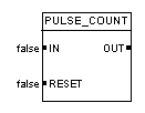 The PULSE_COUNT symbol functions as a counter that counts the positive flanks going through the signal. Which means that whenever the input signal changes from false to true the counter will count up. The counter is reset to zero when it receives a true on its "RESET" input.
DELAY
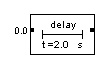 The DELAY symbol functions as a time dampener that handles its double or integer input value as a setpoint, reaches it with a step response and returns the processed double value as its output. The "T_Value" tag of this symbol is affecting the step response, see the formula below.
\$V_(t) = V_(0) e^(-t/τ)\$
\$V_(t)\$ |
Current value |
\$V_(0)\$ |
Initial value |
\$e\$ |
Euler’s number |
\$t\$ |
time passed |
\$τ\$ |
time constant |
Comparators
EQ
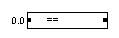
 The EQ symbol functions as a equal to comparator and compares its integer or double inputs to each other. If they are equal the symbol will return a boolean true as output. The left side of this symbol contains a plane for inputs and the right side a plane for outputs. The left input plane is limited to two inputs and the right output plane can handle multiple outputs.
NE
 The NE symbol functions as a not equal to comparator and compares its integer or double inputs to each other. If they are not equal the symbol will return a boolean true as output. The left side of this symbol contains a plane for inputs and the right side a plane for outputs. The left input plane is limited to two inputs and the right output plane can handle multiple outputs.
GE
 The GE symbol functions as a greater than or equal to comparator and compares its integer or double inputs to each other. If the upper input is greater than the lower input or if they are equal the symbol will return a boolean true as output. The left side of this symbol contains a plane for inputs and the right side a plane for outputs. The left input plane is limited to two inputs and the right output plane can handle multiple outputs.
GT
 The GT symbol functions as a greater than comparator and compares its integer or double inputs to each other. If the upper input is greater than the lower input the symbol will return a boolean true as output. The left side of this symbol contains a plane for inputs and the right side a plane for outputs. The left input plane is limited to two inputs and the right output plane can handle multiple outputs.
LE
 The LE symbol functions as a lower than or equal to comparator and compares its integer or double inputs to each other. If the upper input is lower than the lower input or if they are equal the symbol will return a boolean true as output. The left side of this symbol contains a plane for inputs and the right side a plane for outputs. The left input plane is limited to two inputs and the right output plane can handle multiple outputs.
LT
 The LT symbol functions as a lower than comparator and compares its integer or double inputs to each other. If the upper input is lower than the lower input the symbol will return a boolean true as output. The left side of this symbol contains a plane for inputs and the right side a plane for outputs. The left input plane is limited to two inputs and the right output plane can handle multiple outputs.
COMPARE
 The COMPARE symbol functions as a comparator with a multiple choice option for which operator is used for comparison. The operator is chosen by adjusting the internal variable "OPR" in the logic content, see the table below for how the operators are indexed on this value. The symbol will compare its double or integer input value to the internal variable "CNST" in the logic content with the chosen operator. The symbol will return a boolean output dependent on the input and settings given.
| Index | Operator |
|---|---|
0 |
= |
1 |
>= |
2 |
⇐ |
3 |
> |
4 |
< |
5 |
!= |
Math
MAX
 The MAX symbol functions as an mathematical operation that returns the maximum of all double or integer input values. The left side of this symbol contains a plane for multiple inputs and the right side a plane for outputs.
MIN
 The MIN symbol functions as an mathematical operation that returns the minimum of all double or integer input values. The left side of this symbol contains a plane for multiple inputs and the right side a plane for outputs.
ADD
 The ADD symbol functions as an mathematical operation that returns the sum of all double or integer input values. The left side of this symbol contains a plane for multiple inputs and the right side a plane for outputs.
SUB
 The SUB symbol functions as an mathematical operation that returns the subtraction of the most upper double or integer input value with the rest of all the double (or integer) input values underneath. The left side of this symbol contains a plane for multiple inputs and the right side a plane for outputs.
MUL
 The MUL symbol functions as an mathematical operation that returns the multiplication of all double or integer input values. The left side of this symbol contains a plane for multiple inputs and the right side a plane for outputs.
DIV
 The DIV symbol functions as an mathematical operation that returns the division of the upper double or integer input value with the double or integer input values underneath (OUT = I0 / I1 / I2 / I..). The left side of this symbol contains a plane for multiple inputs and the right side a plane for outputs.
CURVE
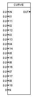
The CURVE symbol functions as a look-up function for reading out the appropriate value based on a curve. The curve is implemented by filling in the inputs X1 to X8 and Y1 to Y8 and the input N is used for determining the amount of X and Y points used for the curve. It looks at the X-axis with the double value of input IN and looks up the corresponding value on the Y-axis to return as an double output. The symbol displays on the left side all the input values for the curve and curve length.
| Name | Type | Data type | Function |
|---|---|---|---|
IN |
Input |
Double |
Input variable |
X1 to X8 |
Input |
Double |
X Data points of the curve |
Y1 to Y8 |
Input |
Double |
Y Data points of the curve |
N |
Input |
Integer |
Input for amount of data points used |
OUT |
Output |
Double |
Returning Y value from the curve dependent on input variable |

Math Functions
ABS
 The ABS symbol functions as a mathematical function that returns the absolute value of the double or integer input value as output.
SQRT
 The SQRT symbol functions as a mathematical function that returns the square root of the double or integer input value as output.
LN
 The LN symbol functions as a mathematical function that returns the natural logarithm of the double or integer input value as output.
EXP
 The EXP symbol functions as a mathematical function that returns the exponential function of the double or integer input value as output.
LOG
 The LOG symbol functions as a mathematical function that returns the logarithm of the double or integer input value as output.
POW
 The POW symbol functions as a mathematical function that returns the double or integer input value to the power of the adjustable internal variable "POWER" in the logic content as output.
PI
 The PI symbol functions as a mathematical constant that returns the double value of PI (\$pi\$) as output.
E
 The E symbol functions as a mathematical constant that returns the double value of Euler’s number (e) as output.
RANDOM
 The RANDOM symbol functions as a mathematical function that returns a random double value between 0 and 1 as output.
SIN
 The SIN symbol functions as a mathematical function that returns the sine of the double input value as output.
COS
 The COS symbol functions as a mathematical function that returns the cosine of the double input value as output.
TAN
 The TAN symbol functions as a mathematical function that returns the tangent of the double input value as output.
ASIN
 The ASIN symbol functions as a mathematical function that returns the arcsine of the double input value as output.
ACOS
 The ACOS symbol functions as a mathematical function that returns the arccosine of the double input value as output.
ATAN
 The ATAN symbol functions as a mathematical function that returns the arctangent of the double input value as output.
RAD2DEG
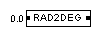 The RAD2DEG symbol functions as a conversion of the double input of an angle in radian to the output in degrees.
DEG2RAD
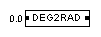 The DEG2RAD symbol functions as a conversion of the double input of an angle in degrees to the output in radian.
INTEGRATOR
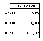 The INTEGRATOR symbol functions as a mathematical function that returns the double or integer input value integrated over time as output. Which means the input adds depending on the time to the total as an output. It also has a function for determining if a upper or lower level boundary is reached with the double inputs "UL" and "LL" and this will return a boolean true value for the outputs "OUT_UL" or "OUT_LL".
\$y_(n) = y_(n-1) + x_(n) * dt\$
\$y_(n)\$ |
Current output |
\$y_(n-1)\$ |
Result from previous cycle |
\$x_(n)\$ |
Current input |
\$dt\$ |
Updated time per cycle |
| Name | Type | Data type | Function |
|---|---|---|---|
IN |
Input |
Double |
Input variable |
UL |
Input |
Double |
Upper limit |
LL |
Input |
Double |
Lower limit |
OUT |
Output |
Double |
Summed itself with input variable at each time interval |
OUT_UL |
Output |
Boolean |
Upper limit reached |
OUT_LL |
Output |
Boolean |
Lower limit reached |
DIFF
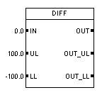 The DIFF symbol functions as a mathematical function that returns the double or integer input value differentiated over time as output. Which means it returns the difference in input over a time-step as an output. It also has a function for determining if a upper or lower level boundary is reached with the double inputs "UL" and "LL" and this will return a boolean true value for the outputs "OUT_UL" or "OUT_LL".
\$y_n = ( x_n - x_(n-1) ) / dt\$
\$y_(n)\$ |
Current output |
\$x_(n)\$ |
Current input |
\$x_(n-1)\$ |
Input from previous cycle |
\$dt\$ |
Updated time per cycle |
| Name | Type | Data type | Function |
|---|---|---|---|
IN |
Input |
Double |
Input variable |
UL |
Input |
Double |
Upper limit |
LL |
Input |
Double |
Lower limit |
OUT |
Output |
Double |
Returns difference between current and previous input variable |
OUT_UL |
Output |
Boolean |
Upper limit reached |
OUT_LL |
Output |
Boolean |
Lower limit reached |
Ramps
RAMP
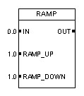 The RAMP symbol functions as a ramp function that treats its double input value as a setpoint and reaches this setpoint in a lineair way with fixed steps that are determined by the double inputs "RAMP_UP" and "RAMP_DOWN". It returns the processed value as output.
| Name | Type | Data type | Function |
|---|---|---|---|
IN |
Input |
Double |
Setpoint for ramp |
RAMP_UP |
Input |
Double |
Step size ramping up |
RAMP_DOWN |
Input |
Double |
Step size ramping down |
OUT |
Output |
Double |
Returns ramped value |
Signal Converters
CONV_DI
 The CONV_DI symbol functions as converter that converts a double value as input to a integer value as output. In this process the value gets rounded to the nearest integer.
CONV_DB
 The CONV_DB symbol functions as converter that converts a double value as input to a boolean value as output. In this process the value gets rounded to the nearest whole number and then returns a false if it’s equal to or lower than a zero, otherwise it will return a true.
CONV_ID
 The CONV_ID symbol functions as converter that converts a integer value as input to a double value as output.
CONV_IB
 The CONV_IB symbol functions as converter that converts a integer value as input to a boolean value as output. It returns a false if it’s equal to a zero, otherwise it will return a true.
CONV_BD
 The CONV_BD symbol functions as converter that converts a boolean value as input to a double value as output. If the boolean is false it returns a 0.0 and if it’s true it returns a 1.0 as value.
CONV_BI
 The CONV_BI symbol functions as converter that converts a boolean value as input to an integer value as output. If the boolean is false it returns a 0 and if it’s true it returns a 1 as value.
BIT
 The BIT symbol functions as a decimal to binary converter that returns a single bit as its boolean output depending on the position in the binary number. This position is determined by the internal integer variable "BIT_NR". The decimal is assigned by the integer input value.
BITS
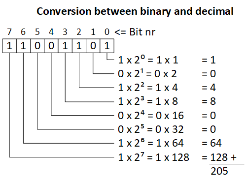
 The BITS symbol functions as a binary to decimal converter that converts multiple boolean inputs to an integer value as output. The left side of this symbol contains a plane for multiple boolean inputs and the right side a plane for the integer output. The symbol expects a 32 bits on its input plane for forming the integer and reads the inputs from top to bottom, meaning the top bit corresponds with the lowest bit-value and the 32th bit in the row will produce an overflow to the integer. When the amount of 32 bits is exceeded the symbol will just add the newly created 32-bit integer values produced to its output.
STD
T_ADM
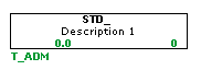 The T_ADM symbol is used to group states within a state transition diagram (STD) in PsxCad. PsxCad uses STD symbols to visualize STDs, creating a clearer picture of what happens. STDs are used to control a module, containing multiple states corresponding to the amount of functions. The T_ADM symbol ensures that only one state within its corresponding group can be active. It uses an internal integer, corresponding to the active state, to keep track. Each STD requires a separate T_ADM symbol with a ID tag that must be the same as the ID tag of each state, without the alternating integer.
STATE
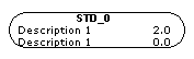 The STATE symbol is used to define a state within a state transition diagram (STD) in PsxCad. PsxCad uses STD symbols to visualize STDs, creating a clearer picture of what happens. STDs are used to control a module, containing multiple states corresponding to the amount of functions. The states are grouped together with the T_ADM symbol. Because of this, each state symbol is expected to have a ID-tag that starts with the name of the T_ADM symbol, followed by a integer number of choice. Within this group only one state can be active at a time, ruling out any unwanted ghosting behavior. When a state connected to this state is active, this state can become active when the conditions of the transition line are met. This state also becomes active if a adjacent, floating transition lines conditions are met.
TRANSITION
 The TRANSITION symbol is used to define the transition to a state within a state transition diagram (STD) in PsxCad. PsxCad uses STD symbols to visualize STDs, creating a clearer picture of what happens. STDs are used to control a module, containing multiple states corresponding to the amount of functions. A transition line is used to change the active state. When it’s connected to two states and the state at the back of the arrow is active, activating the condition of the line will change the active state to the state on the side of the arrowhead. When a transition line is floating, with only a state connected to the arrowhead, the state will become active when the condition is activated, regardless of which state was active before. The ID tag can be relocated by pressing with the left mouse-click on it.
Controllers
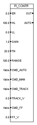
PI_CONTR
| Name | Type | Data type | Function |
|---|---|---|---|
ER |
Input |
Double |
Error between setpoint and process value (SP-PV) |
HL |
Input |
Double |
Higher limit, sets signal size for control signal |
LL |
Input |
Double |
Lower limit, sets signal size for control signal |
GAIN |
Input |
Double |
Proportional gain factor |
TN |
Input |
Double |
Integral time constant |
RANGE |
Input |
Double |
Scales incoming error relative to output |
CMD_AUTO |
Input |
Boolean |
Command to trigger automatic mode |
CMD_MAN |
Input |
Boolean |
Command to trigger manual mode |
CMD_TRACK |
Input |
Boolean |
Command to trigger tracking mode (Bypassing symbol functions) |
TRACK_V |
Input |
Double |
Forced control signal in tracking mode |
CMD_FF |
Input |
Boolean |
Command to trigger feed forward option (extends algorithm with optional parameter) |
FF_V |
Input |
Double |
Input parameter for feed forward option |
OUT |
Output |
Double |
Returns control signal of PI controller |
AUTO |
Output |
Boolean |
Returns current state (automatic or manual) |
The PI_CONTR symbol functions as a proportional integral (PI) controller (or PIC). Depending on its input and settings this controller produces a control signal as output for actuators in the processes of a plant, such as control valves, VFD motors or pumps. The operation of a PI controller is shown in a block diagram in Figure 6. In this block diagram the part of the controller that lies within the scope of this symbol is highlighted by a blue dashed line. The symbol expects the error value, a subtraction of the process value from the setpoint, for its double input ER. By taking the error as input variable the PI controller can be easily inverted by subtracting the setpoint from the process value instead of the other way around.
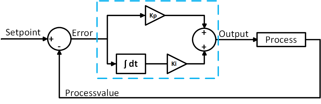
The PI controller will react to its error input based on its input settings from the inputs GAIN and TN. These are tuning parameters. GAIN is the parameter for the proportional gain (also known as \$K_(p)\$) and TN is the parameter for the integral time constant in seconds (also known as \$T_(i)\$). Together they form the parameters needed to solve the equation within the PI controller to get the output OUT. See the PI controller equation below. The equation used in this symbol is the velocity form of the PID algorithm without the derivative part.
\$y_(n) = y_(n-1) + ( e_(n) - e_(n-1) ) * K_(p) + e_(n)*dt (K_(p))/T_(i)\$
\$y_(n)\$ |
Current output |
\$y_(n-1)\$ |
Output from previous cycle |
\$e_(n)\$ |
Current error |
\$e_(n-1)\$ |
Error from previous cycle |
\$K_(p)\$ |
Proportional gain |
\$T_(i)\$ |
Integral time constant |
\$dt\$ |
Time since previous cycle |
The double input RANGE will scale the incoming error signal in the equation relative to the output. It is configured as a percentage. In the basic symbol library of Powerspex this is set to a 100% as a default.
The output of the controller is limited between the values of inputs HL (higher limit) and LL (lower limit). This way the control signal won’t exceed certain boundaries of the hardware, like a 4-20 mA or 0-24 V signal. In the basic symbol library of Powerspex this is set to a 0-100% signal limit as a default.
The controller can be switched between automatic and manual mode with the boolean inputs CMD_AUTO and CMD_MAN. It uses the boolean output AUTO to keep track of its current mode, this will be false when it is in manual mode and true when it is in automatic mode. The output gets written by the equation for the PI controller in automatic mode, while in manual mode nothing will write the output. This way the user is able to change the output value themselves while in manual mode. This can be done by hand in the logic content window of the symbol or overwritten by an other symbol elsewhere outside of this symbol for example an OUT or MOVE symbol. The higher and lower limits are still valid in this case.
The controller can be set to tracking by setting the boolean input CMD_TRACK. This means that, whatever the current mode of the PI controller, its functions will be bypassed by overwriting the output OUT directly with the signal from the double input TRACK_V. The higher and lower limits are still in affect. See the equation below for the mathematical approach of this effect.
\$y_(n) = T_(n)\$
\$y_(n)\$ |
Current output |
\$T_(n)\$ |
Tracking value |
In addition to the calculation of the PI controller equation a feedforward option can be applied by setting the boolean input CMD_FF. The feedforward option is meant to anticipate the possible delayed effects within the process. This feedforward option lets the differential changes of the signal from the double input FF_V be added to the equation. By doing this the controller can anticipate on a signal that comes earlier in the process. When there is little change in this signal, the feedforward part will react less to this than when there is a lot of change in the signal.
\$y_(n) = ... + x_(n) - x_(n-1)\$
\$y_(n)\$ |
Current output |
\$x_(n)\$ |
Current feedforward value |
\$x_(n-1)\$ |
Previous feedforward value |
Revisions
NOTE
 The NOTE symbol functions as a note for documentational purposes. It allows for 10 rows of text to be added to the note. The lines of text are adjustable with the variables "TEXT1" to "TEXT10" in the symbol parameters.
COMMENT
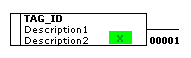
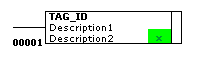
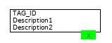
 The COMMENT symbol functions as a comment for documentational purposes. It allows for 2 rows of text to be added to the comment. The lines of text are adjustable with the variables "TEXT1" to "TEXT2" in the symbol parameters.
REV
 The REV symbol functions as a display of revision numbers for documentational purposes. The number is adjustable with the variable "REV" in the symbol parameters.


Miscellaneous
PAGE_BREAK

The PAGE_BREAK symbol is used to enforce an certain order in the execution of the logics on the page. PsxCad executes each logic page separately and executes the logics from left to right on each page. This symbols allows the option to split a logic page in order to execute the logic above and below this symbol separately. The logics above this symbol will be executed first and the logics below after. This symbol can be used on a page as many times you want. This function can become essential while working with typical pages, where there is only one page that can be used for generating a typical block. When printing your logic pages this symbol will also split the pages.
LOAD_DATA
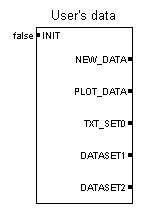
The LOAD_DATA symbol is used to import external data into PsxCad. It features multiple inputs and outputs, with their respective functions explained below. Important to note is that this symbol can be easily customized through code to meet specific user preferences. As a result, you may come across different versions of this symbol in other projects.
The symbol requires a text file with multiple columns of data points, where the columns are separated by tabs. As shown in the example below, you can create data sets in Excel and save them as a text file with the columns separated by tabs to easily set up your data profile.
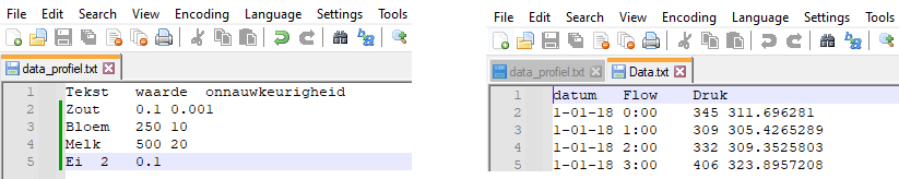
When INIT is set to true, the script prompts the user to select a text file using a file chooser. Typically, a push button on the HMI is connected to this input, allowing users to easily select the desired file. Once a file is selected, the script reads its contents and converts them into an array, which contains several variables. The first column of the data file is stored in a variable named TEXT_SET0, and the subsequent columns are each stored in their own variables, such as DATA_SET1, DATA_SET2, and so on.
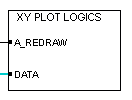
When a new data profile is loaded into the symbol, it triggers the NEW_DATA output, which can be used to activate other functions or symbols. Additionally, the PLOT_DATA output stores one of the datasets in a variable, which can be used to create graphical representations of the selected dataset using (for example) the XY_PLOT_LOGICS symbol.
| Name | Type | Data type | Function |
|---|---|---|---|
INIT |
Input |
Boolean |
When triggered, the user will be prompted to select data file to load. |
NEW_DATA |
Output |
Boolean |
This output is triggered when a new dataset is loaded. |
PLOT_DATA |
Output |
Object |
One dataset can be stored into this variable, which can then be utilized to create graphical representations of the selected dataset. |
TXT_SET0 |
Output |
String |
Stores first column of the dataset in the data file. |
DATASET1 |
Output |
Object |
Stores second column of the dataset in the data file. |
DATASET2 |
Output |
Object |
Stores third column of the dataset in the data file. |
Related topics: Data profile