User interface
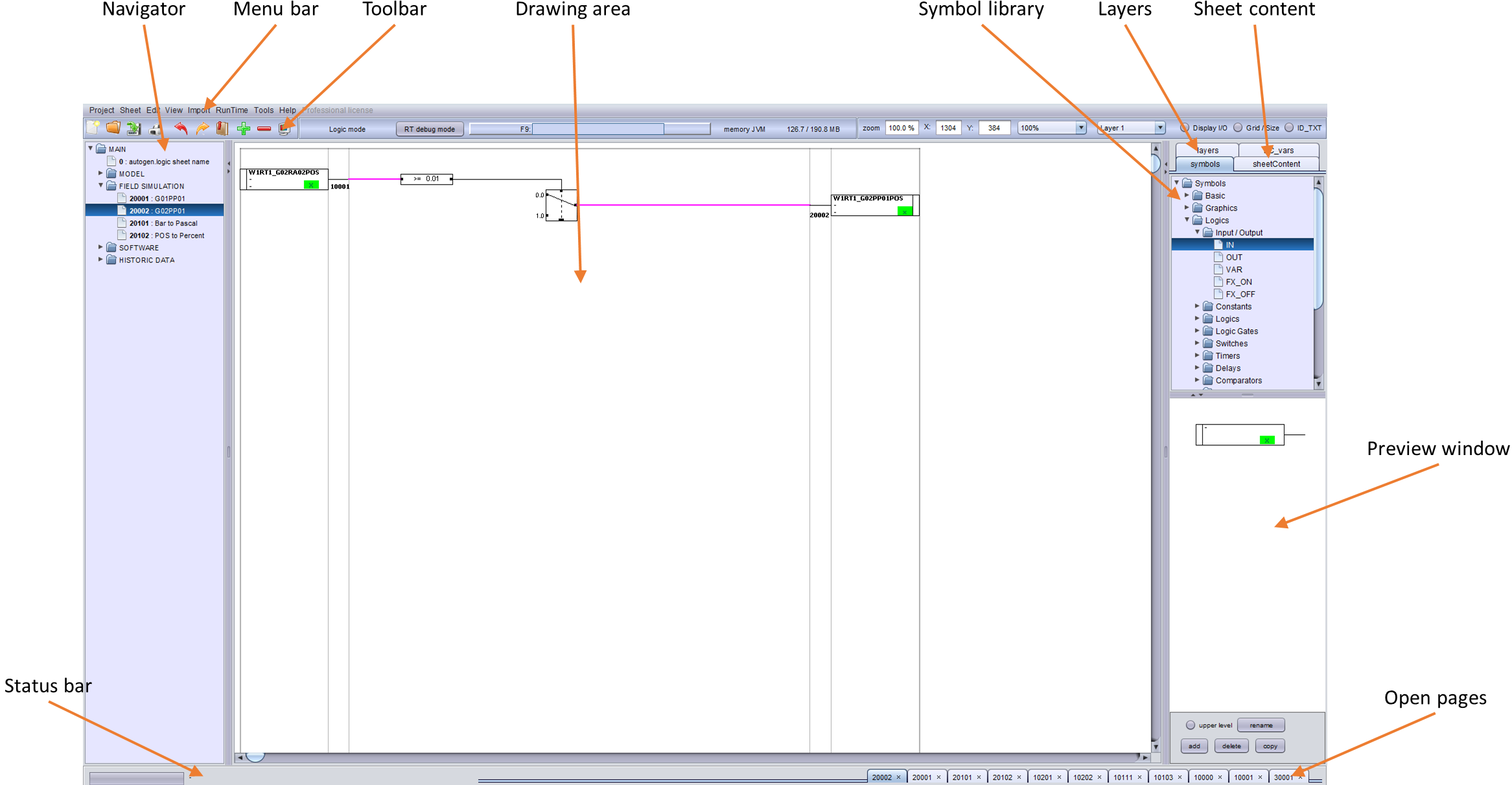
The PsxCad user interface is the main screen that shows up on start up. The user interface consists of multiple components, each with their own location on the screen, as shown in the example above.
Menu bar

The menu bar consists of a number of drop-down menu`s. Within these drop-down menu`s, multiple functions of PsxCad can be started.
These drop-down menu`s, and what they entail, are summarized as follows:
Project
The Project-tab has options for saving and loading project. It can open new projects or print screens of importance.
Sheet
The Sheet-tab has options to open new sheets in the navigator window, resizing, copying and renaming sheets in the drawing area and to view parameters used in the current drawing area.
Edit
The Edit-tab has options to change the database, different trees, alarm parameters, color tables and synchronization between parts.
View
The View-tab can change the current drawing mode, bring up the symbol library and has multiple overview options for the project.
Toolbar
The toolbar consists of three parts.
Left part
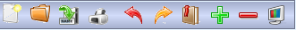
The leftmost part has icons that work as buttons. When hovering the mouse over a button, text appears displaying it`s function. The following buttons are available in this toolbar:
- New project
-
Opens a new project.
- Open project
-
Opens an existing project from a input file with an .jdx-extension.
- Save project
-
Saves the current project as a .jdx-file.
- Print sheet
-
Prints one or more sheets of the project.
- Undo action
-
Undoes the last action.
- Redo action
-
Redoes the last action.
- Symbol library
-
Opens the symbol library window.
- Zoom in
-
Zooms in with 10% of the standard size.
- Zoom out
-
Zooms out with 10% of the standard size.
- Zoom 100%
-
Resets zoom to 100% of standard size.
Middle part

The middle part consists of miscellaneous options. Some of these options will disappear depending on the size of the window. The following functions are available:
- Drawing mode
-
Drawing mode shows the current operating mode. Possible options are:
-
Screen mode
-
Logic mode
-
Cadre mode
-
- RT debug mode
-
This button starts a runtime in Debug mode.
- F9
-
This button opens the last project that was worked on. Pressing the F9-key gives the same result. This button shows the name of the last saved project after opening a project.
- Memory JVM
-
This shows the memory-usage of the Java Virtual Machine (JVM). The first number is the current usage of memory, while the second is the memory reserved for use by JVM.
Right part

The right part gives display options for the screen. The following functions are available here:
- Zoom
-
Shows the current zoom level, with 100% being the standard size.
- X
-
Shows the X-coordinate of the cursor in pixels.
- Y
-
Shows the Y-coordinate of the cursor in pixels.
- Grid
-
Allows selection of a grid from a drop-down box.
- Layer
-
Allows selection of a drawing layer from a drop-down box.
- Display I/O
-
This will show the inputs and outputs of logic blocks in logic mode when active.
- Grid/Size
-
This will show the grid and window size of the current screen when active.
- ID_TXT
-
This will show the ID of the symbols on the screen when active.
Navigator window
The navigator window gives an overview of the available pages within the project.
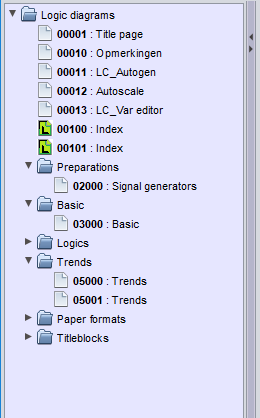
The pages shown are dependent on the drawing mode active:
- Screen mode
-
The navigator shows the graphics-pages.
- Logic mode
-
The navigator shows the logic pages.
- Cadre mode
-
The navigator shows the cadre drawings.
The pages can be ordered and separated by folders. When clicking on a page, that page will appear on the drawing area. On the bottom right a tab will be opened with the page number that was opened.
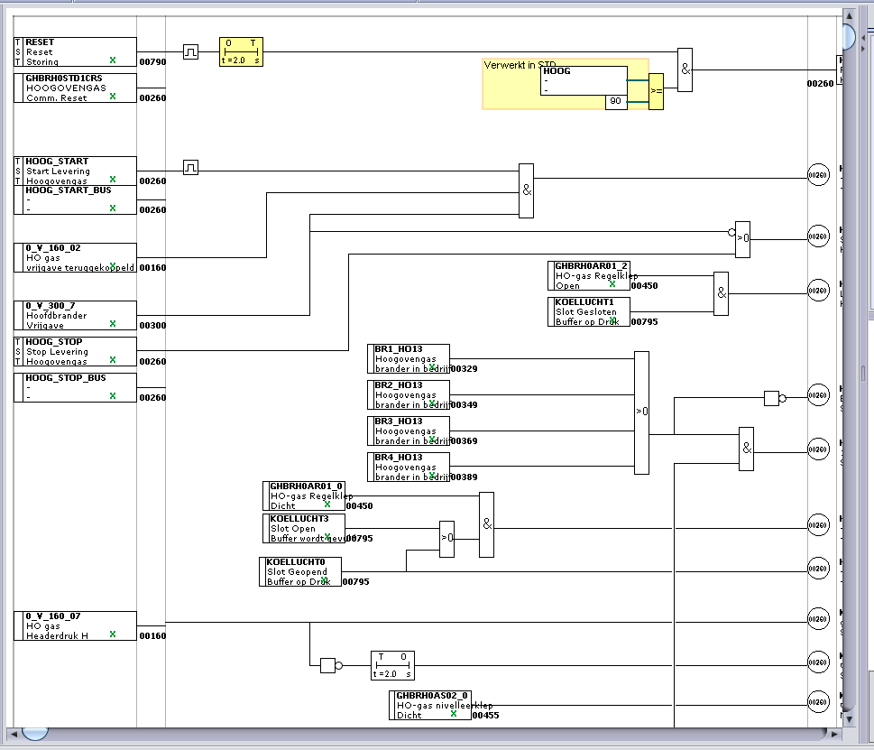
Drawing area
The drawing area shows the contents of the current page.
The page shown is dependent on the drawing mode selected:
- Screen mode
-
The drawing area shows a graphics-page.
- Logic mode
-
The drawing area shows a logic page.
- Cadre mode
-
The drawing area shows a cadre-drawing.
The drawing area is used to create or edit pages.
On the right side and on the bottom of the drawing area are two sliders, which can be used to move the drawing. The drawing can be zoomed in or out by using the zoom-buttons on the toolbar.
Symbol library
The symbol library is shown on the right side of the screen beneath the tab “symbols”.
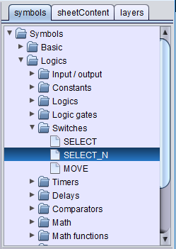
The symbol library shows all symbols that have been configured in the current project. These symbols have been partitioned with folders.
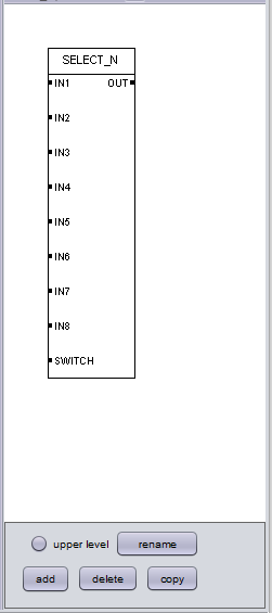
Selecting a symbols shows it on the preview window. Clicking twice on the symbol pairs it with the cursor to move it to the drawing area. Clicking again will release the symbol on the drawing area where the cursor was hovering.
Sheet content
Sheet content is shown on the right side of the screen underneath the tab “sheetContent”.
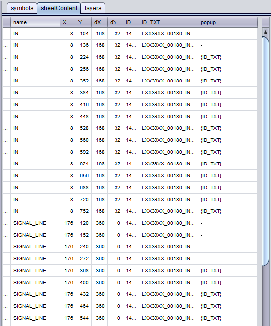
Sheet content shows an overview of all symbols on the opened page. Some of the more important attributes of these symbols are also shown here.
Sheet content is a useful tool for creating graphic pages. Using it allows for easy selection of symbols or editing of parameters.
Layers
The tab “layers” on the right side of the screen shows an overview of the different layers.
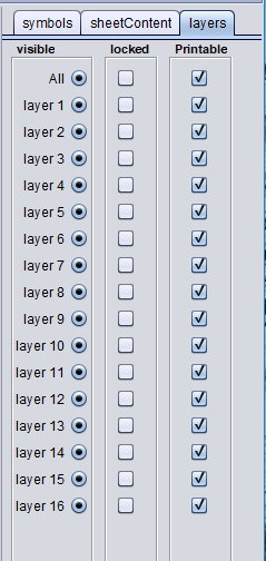
There are 16 layers available, all of which can be used for drawing. The layer currently used for drawing is the one selected through the toolbar. The following options are available for each layer:
- Visible
-
Makes the contents of this layer visible.
- Locked
-
Locks the contents of this layer so that it can`t be changed.
- Printable
-
Gives instructions to add this layer when printing.
Status bar
The status bar is located at the bottom left of the screen.

The status bar is made up of two components. The left part is a progress bar that is used when the program is in progress with a task. Examples include saving and loading a project-file.
The right part of the status bar shows information on either what the program is processing or the symbol that the cursor is hovering over. A breakdown of the info shown in the example above is as follows:
- 184 : IN
-
The number and name of the symbol in the symbol library.
- X=8
-
The X-coordinate of the symbol on the page.
- Y=488
-
The Y-coordinate of the symbol on the page.
- dX=168
-
The width of the symbol on the page.
- dY=32
-
The height of the symbol on the page.
- ID : SIN_SIGNAL
-
The ID name of the symbol (Tag, KKS-code).
- spec param : USER:VALUE
-
The input value of special parameter(s).
Open pages
Opened pages will be shown in the tabs on the bottom right of the screen.
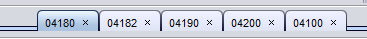
Whenever a new page is opened, a tab appears on the bottom right of the screen with the page name. The order of these tabs is from right to left, with the newest tab opened on the left.
Clicking on a tab opens that specific page. This allows quick switching between active pages. A tab can be closed by pressing the x on the tab.
Search window
The search window is opened with the z-key.
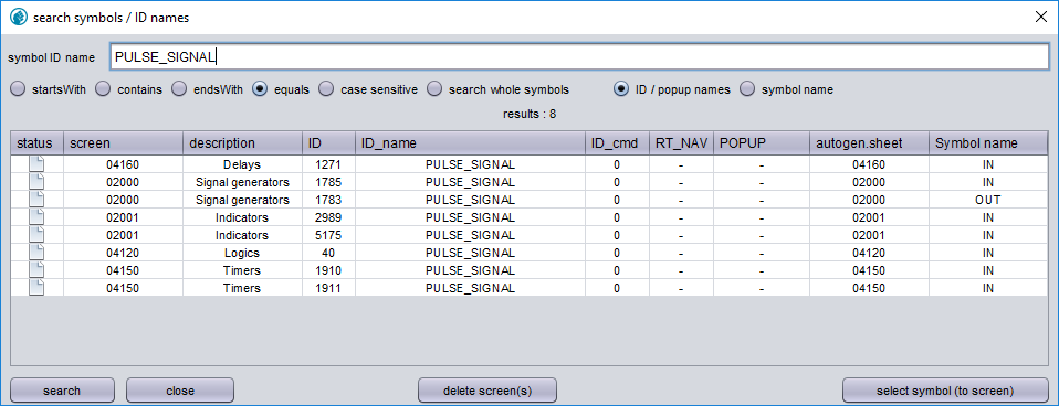
The search window allows for the searching of symbols. In the example shown above, the ID name “PULSE_SIGNAL” is input and the option “equals” is selected. By clicking “search”, located at the bottom, a list will appear with all symbols whose ID name is “PULSE_SIGNAL”. These symbols can be graphic-, logic- or model symbols.
Clicking twice on one of the search results will open the page this symbol is located on and highlights the symbol with a flashing border.