Creating a State-Transition Diagram
A step by step guide
Step 1: Admin symbol
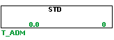
The first step in creating a STD is to make a T_ADM symbol. The name of this symbol cannot end with a digit, since later this will be used to keep track of the states. The T_ADM symbol is used to group states within a state-transition diagram. Each STD requires one T_ADM symbol.
Step 2: States
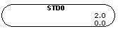
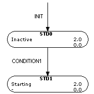
The next step is to add the first state. This will be the initial state of the system. The states have the following name convention: STDNAME0, where it should have the exact same name as the T_ADM symbol followed the number of the state, which is 0 for example in the initial state. One property of a state is that when the state is active, its tag will be set to true which can be used conveniently in the logics.
Step 3: Transitions
Transitions are used to move from state to state. A transition will be done when the condition of a transition that departs from the current state is true. At the moment the simulation is started you want the state to be in the initial state. Normally this is already the case, but we will add our first transition to enforce this. To add a transition use the shortcut T from the point you want your condition to start, followed by a left-click.
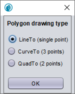
A pop-up shows up, like the one in the figure above. In here, one can choose between multiple options for the shape of the transition line. Choose one and then connect the condition by right-clicking on the edge of the initial state.
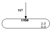
It can be seen that the transition does not depart from a state, in this case the system is not required to be in a certain state for the transition to be done.
Step 4: Adding states
Now we can add our next state to the STD. Create the new state with the same name convention but now with the consecutive number of the last state. Start a new transition in the same manner as described before and use it to connect the edge of the previous state to the next state. To have an overview of what every states entails it is possible to add a description using the shortcut g on the state.
Step 5: Logics
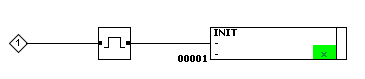
The conditions in the system can either be triggered by certain events in the process or a user input. You have to define the logics to determine in what case conditions are met. To reach the initial state one can use the following procedure, where the condition will be set to true for one timestep at the start of the simulation. This transition can also be used to reset the STD by hand in runtime mode.
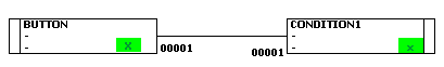
As an example we will create a boolean variable that is triggered when a button is pressed. This boolean will trigger CONDITION1 and subsequently the next state is reached.
Step 6: Testing in simulation
At this point we should have a working STD. We can test this by observing the simulation. After the simulation is started the system should be in the initial state, this is indicated by the fact that the state symbol is green. After the button is pressed, the state should switch from STD0 to STD1.
Advanced State-Transition Diagrams
The obtained STD is very simple and only the start of STDs that are commonly used. However, by repeating the steps introduced before, we can build more complicated STDs by adding new transitions, states and logics. It is even possible to have multiple state options start from a former state. Also, it could be the case that the process cycles back to a former state. See the image below for an example.
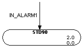
Alarms
Another possible state is an alarm state. It is common practice to indicate alarms with numbers starting from 90 and higher. It is possible to enter the alarm state from any state, therefore it can be implemented as in the figure below. If the condition for the alarm is true, the system will be forced to enter the alarm state. The cause of the alarm must be resolved before the system can enter any other state. After the alarm is resolved the system can be reset by running the initial condition.
Timers
An additional feature of STDs are the timers. Every state contains the variables TL and TH, where TL is the minimum time the state is required to be in. If one of the conditions of the transitions will be met within this time, it will not happen until the minimum time is met. On the other hand, the maximum time of the state is described by TH. In case this is reached, this will denoted by a boolean in the current state as well as in the admin. This can be used, for example, to go in an alarm state when the maximum time is reached.