Setup up Modbus communication
On this page a guide on how to set up Modbus communication in PsxCad. There are two options here either PsxCad acts as a client or as a server. In order to connect PsxCad to a Modbus device one should set PsxCad up as a client.
Client mode
Requirements:
-
Basic knowledge of Modbus TCP
-
Psxcad
-
Modbus device that acts as a server
-
The IP of the Modbus device
-
The Address of the Modbus register
More details about Modbus in PsxCad can be found in the reference section Modbus TCP.
Logic editor
Start Psxcad and open the logic editor either by navigating through the menu or using the Crtl+Alt+L shortcut.
Insert an input or output symbol
Open the library and insert a symbol from the directory and give it a tag name.
Configure the Modbus connection
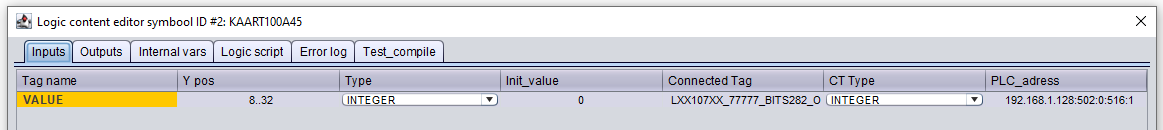
Open the logic content of the symbol with J and enter the communication parameters in the column PLC_adress for each tag. Check client mode for detailed explanation of the parameters and see Figure 1 for an example.
192.168.1.128:502:0:516:1
{server address}:{port}:{Unit ID}:{Modbus address}:{number registers}
Test the communication
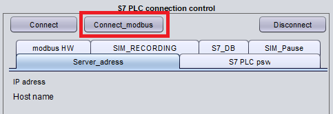
Start PsxCad runtime mode and start the connection by pressing the Connect_Modbus button in the control box at runtime. This button will have to be pressed every time you start a new runtime session. See the figure below.
Setting up Modbus with PsxCad as server
Requirements:
-
Basic knowledge of Modbus TCP
-
PsxCad
-
The IP address of the PsxCad simulation
More details about Modbus in PsxCad can be found in the reference section see Modbus TCP.
Logic editor
Start Psxcad and open the logic editor either by navigating through the menu or using the Crtl+Alt+L shortcut.
Configure the Modbus connection
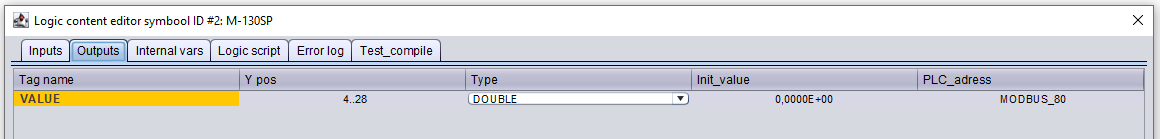
Open the logic content of the symbol with J and enter the communication parameter in the column PLC_adress for each tag. Check server mode for detailed explanation and see Figure 3 for an example.
Setting up a client
In order to let another Modbus device connect to the Modbus server of the simulation as a client. You will need the IP address of your PsxCad simulation. This can be found on the control box in Runtime mode. PsxCad uses also port 502 for his Modbus connection. Set your client up with this IP address and port number.
MODBUS_123
MODBUS_{Modbus address}
Test the communication
Start PsxCad runtime mode. It should detect the presence of tags with a Modbus address referring for a server and set this up within PsxCad automatically. PsxCad will indicate on the control box that a Modbus server is active when the Modbus server is successfully set up. See the figure below.

Set-up Modbus communication within PsxCad
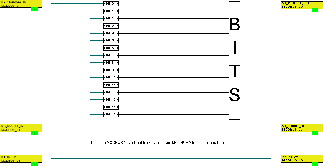
When you would like to communicate booleans (called coils in modbus) over the Modbus, you will use a 16 bit integer to pass the booleans over. For sending booleans, you must convert them into integers using the BITS symbol. For receiving booleans from a Modbus device, you should extract the passed integer into boolean values using the BIT symbol. The integer IN or OUT symbol should contain a Modbus address in both cases.
When you would like to communicate doubles over the Modbus, you must be aware that PsxCad normally uses doubles, but to communicate by Modbus PsxCad will convert its doubles in to two floats. You need to use two registers while numbering your Modbus addresses, because a float contains 32 bits it will occupy two 16-bit registers. The Modbus address used for a double will point to the first register will also occupy the register after it to hold the float. Reading or writing only the second half of such double will cause your troubles.
Setting up Modbus addresses for integers is very straight forward. Since Modbus uses a 16 bit register for each address it is a perfect fit for integers. This means each integer has its own address within the Modbus.